Saturday, January 31, 2009

Bending Brake Lines (Part 2)

I spent a couple of hours this morning and another hour tonight working on brake lines.

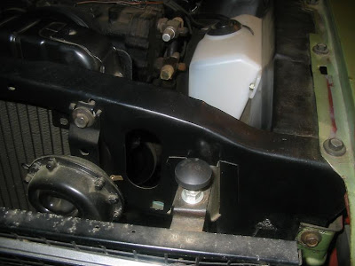
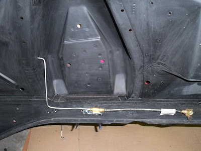
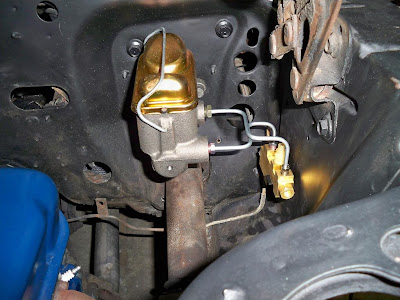
I started with the line across the back of the engine compartment. It was not too difficult considering the number of bends in the piece. I kept the original so I could better duplicate the appearance and location of each bend. In the pictures the lines are just mounting with some old original bolts I've not bothered to clean up yet. The line looks crooked in the picture but it is not.


Since I'm adding disc brakes to the front but using rear drums, I next plumbed in a residual pressure valve. If not for needing this piece, I could have reconnected the original rear line to the proportioning valve. However, I took the opportunity to replace the portion of the line which leads from the proportioning valve to under the driver footwell. I installed the residual pressure valve at this point and then continued with the original line (to be replaced later).
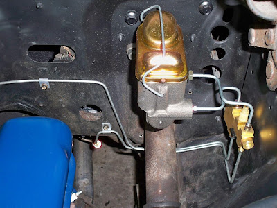


The last step was mounting the rubber caplier hoses so I could bend up lines for each of the front brakes. I completed the passenger side with no trouble. The driver side I wasted three lines of tube creating. Once I had all the bends correct, I then messed up flaring the line. I'll finish this side in the morning. Hopefully, I'll have better luck with it then.
Thursday, January 29, 2009

Timeline Setbacks

In November, I mentioned my wife needed to have surgery. The surgery was postponed but a new date was scheduled for this coming Tuesday. I learned of this around Christmas which prompted me to begin making patch panels. The plan was to have the welding completed so I could paint the engine bay before the surgery.

Once my wife has the surgery, she will be imoble for several weeks. I'll need to take care of the kids and will only have a little time each night to work on the car. I hoped to have the engine bay painted as all of the components are ready for reintall. I could then put a few on each night.

I called the person who is helping me with the welding on January 2nd. He said he would be able to help me and I asked that he call when he had time to fit me into his schedule. I then called 1 1/2 weeks later and left a message. I called another 1 1/2 weeks later and left a message. The last message was left on Monday and I've not heard back.

Since the welding is not done, I'm not sure when I'll be able to finish or what I'll be able to work on for the coming weeks. Unfortunately, this means spring may arrive before the car is in running condition again.

Wednesday, January 28, 2009

Bending Brake Lines (Part 1)

I've spent the evenings this week working on bending brake lines for the Mustang. I decided to test fit, cut and bend the lines before painting the engine bay. This will limit the potential for scratching up the paint later. Additionally, I've not heard back from Danny regarding the welding so I'm running out of things to complete until I get the engine bay welding and paint done.

I would have purchased prebent lines from a Mustang parts vendor but they would not work on my application. I'm using '70 spindles, a reproduction Ford proportioning valve, and a '75 Maverick master cylinder. While this might sound like piecing together random parts they were each selected for a particular reason. However, the connections and lengths no longer match the originals which require I custom build brake lines.

I've never done any brake line work before. I spend the first night test bending a few test lines from metal coat hangers. I the moved on to working with the tube bender on a piece of scrap line I purchased. I succcessfully made one of the lines Tuesday night. I finshed the second line tonight after renting a flaring tool from NAPA at lunch. While it does not look like much, bending the lines and making sure they fit and look well is a task. I pleased so far but have much more brake line work to go.


Sunday, January 25, 2009

Equalizer Bar & Clutch Linkage Restoration

While not originally part of the plan, I recently incorporated the restoration of the clutch linkage.

My decision to restore these parts started when I removed the upper clutch rod. The ends of the rod have plastic bushings but they were completely worn away. The ends of the rod were worn out of shape. Additionally, the bar was from a '65 or '66 and the improper shape resulted in damage to the firewall were it emerges from the passenger area. The firewall was repaired with a hammer and dolly and I purchased the proper clutch rod from NPD.

This rod connects to the pedal and then to what is called the equalizer or z-bar. This bar pivots along a center point which is mounted on one side to the engine block and to the driver side frame rail on the other. When the clutch pedal is pressed, the top part of the bar moves toward the front of the vehicle while the pivot action causes the lower portion to move towards the back of the car. The points were the clutch rod mounts to this piece is worn and needs to be repaired since a replacement is $70.

The final part is another bar which connects to the lower part of the equalizer bar and to the transmission. When the pedal is pushed, this rod moves backwards and disengages the clutch. The mounting point on this piece was worn completely in half. As a result, I needed to purchase replacement from NPD.

I've restored or purchased new parts to complete all parts of the system except the equalizer bar. The bushings for the bar were all worn completely out. Each joint was metal on metal which wore away at the bar. I'll need to have the holes completely welded up and drill new ones. Once that work is done, I'll post a picture of the completely parts.

Saturday, January 24, 2009

Coil Spring Cover Restoration

Below is a picture of one of the two unrestored coil covers which mount in the front fenderwells. These covers are mounted with six nuts and bolts through the fenderwell. They hold a rubber bumper to stop excessive movement of the upper control arm and cover the top of each coil spring.


I stripped the outer surface of these covers on January 3rd. The inside surface is very irregular so the sanding disc I used on the outside was not very helpful. I finished stripping the inner surface using the media blasting cabinet at my parents this weekend. The process was slow because these parts were painted by a dipping process at the factory which left a generous amount of paint on each piece.

I placed the nuts and bolts on on the pieces so I would not lose them. In the picture above, the bolts are actually installed from the wrong side. The bolts have an achor design on them and I have a new set from Mustangs Unlimited which my brother got me for christmas. I blasted the nuts originally used and will repaint them as they are covered with undercoating when installed.

I've put two coats of Kylon primer, Krylon 1613, and 3M 08881 Undercoating on each coil cover.


Sunday, January 18, 2009

Garage Cleanup & General Update

I've not accomplished a large amount over the last two weeks.

Last night I spent a couple of hours cleaning up the garage. This was the second really good cleaning I've done on the garage since the project began. This time I sprayed out the garage with water to get rid of the dirt accumulating around and under the car.

I've just about destroyed the garage floor. It started about two years ago when I replaced both front drive axles in the Honda Accord. Stripping the undercoating and grim from the bottom of the Mustang added to the mess. Finally, I've painted a few suspension parts in the garage and leared how far overspray is spread through the garage. The good news is I received a U-Coat-It floor coating kit for Christmas so I'll repair the situation later this year.

I've gone a little slower with the project over the past two weeks. After building the patch panels, I called Danny requesting some more help with welding. He agreed and we decided he would call me back when convenient for him. I left him a message last Wednesday but have not heard back. I hope he returns my call within the next week as I'm ready to move forward with painting the engine bay.

Friday, January 16, 2009

Arrival of New Proportioning Valve

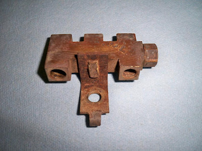
This is the original distribution valve from my '67. There are no identifying marks or numbers cast into the piece. The vehicle was originally equipped with non-power drum brakes. Since the vehicle only had drum brakes, the only function this served was to distribute brake pressure to each of the drums.


My new proportioning valve arrived in the mail on Friday. The piece is produced by MBM (part# PV6070FD) and is modeled after the 1970's style Ford disc/drum unit. The piece includes a valve to direct more of the brake fluid to the front discs. It also includes a metering valve which limits the fluid to the rear drums to avoid lockup.

In the picture below, you can see the new valve along with a few additional parts. These parts include the original bracket I removed from the distribution valve (and painted), the switch which came with this piece (2 posts) beside the original one (1 post) which I plan to reuse, and finally the red part is a 10lbs residual presure valve.


The residual pressure valve is installed in the rear brake line. It is used to hold 10 pounds of presure on the rear brake system. This slightly works against the springs in the rear drum to keep the shoes close (but not touching) the drums. When the brake pedal is pressed, this ensures the rear brakes react as quickly as the front brakes. I'm not sure were I'll put this piece as it will likely standout under the hood.

The picture below shows the assembled new part. The only tricky part was using a hammer to 'smash' a brass bar which extends through the original bracket. This mimics how the bracket was attached to the original distribution valve. I scratched up the braket a little during the process and touched it up. I ended up with a little too much paint on the bracket but its not visible once installed.

Wednesday, January 14, 2009

New Distributor Cap & Rotor

I regularly check eBay for original or cheap parts I could use. I watch them and check back occassionally until the auctions end.

I came home for lunch today and happened to check eBay. A new distributor cap and rotor I started watching was set to end later during the day. I marked it because I need a new cap and this one started at $.99 with free shipping. I placed a maximum bid of $3.00 and returned to work. When I came home, I found I had won the parts for $1.04 (again free shipping).

A small victory but it is nice to find a deal when working on your car because everything cost more than you expect.

02/07/09 Update: The distributor cap and rotor has not arrived. The individual who listed the part on eBay is not responding to my emails. I suppose I should be thankful I'm only out $1.04. Sometimes, you just can't win!

Sunday, January 11, 2009

Spindle & Brake Rotor Assembly

I assembled the spindle with new components I ordered from NPD. The bearings and other parts used to assemble the rotor and spindle were produced by National which is a division of Moog/Federal Mogul. The following parts were needed:

Dust Shield Gaskets (NPD#2B160-2A)
Hub Seal (Part# 6815/NPD# 1190-4)
Inner Bearing (L68149/NPD# 1201-4)
Outer Bearing (LM12749/NPD# 1216-4)
Spindle Nut Kit (NPD# 1195-3K)
Hub Cap (NPD#1131-1)

I did not install new races for the bearings as the rotors are practically new and the set the previous owner installed appear perfect. While this does not seem like an expensive project, the parts listed about cost $55.35. This is why projects end up costing more than expected as one does not think about the prices of these small components when installing a brake system. However, I feel good about the parts used as they are very good quality parts.

The assembly of the spindle was pretty straight forward. The image below shows how the entire assembly is put together.


The spindle assembly was not difficult to put together. Instructions are available in most restoration guides. The only part not really covered is the proper way to grease bearings. If not greased properly, bearings will have a short life because of the stress and heat they are under. The following video from YouTube shows the best way to grease a bearing.
http://www.youtube.com/watch?v=agxjGtmHV_4

I used Valvoline SynPower synthetic grease for the bearings. The grease protects the bearings from -40 degrees up to 400 degrees. The grease is made for use in disc brake systems and in suspension components. Once I purchase a grease gun, I'll use the same grease for all of my suspension components.

Saturday, January 10, 2009

Proportioning Valve Purchase

I've come to trust the products I order from NPD without question. They sell the best quality parts, have everything in stock, and have excellent customer service. However, I experienced my first problem with an order from NPD.

I ordered a new proportioning valve for the Mustang from NPD. I wanted something original looking (no adjustable, knob style piece). While there are many places available for less, I purchased the piece (NPD# 2B091-20BA) from NPD. I trusted it would be the best of the parts available but I was incorrect.


The piece arrived in a box with an MBM logo and no instructions. I opened the box and found the piece was much larger than expected. Due to the size, it was clear it could not go in the original location. The size of the low brake fluid sender was also too large for the stock connector.

I decided to go ahead and find installation instructions on the internet. Using the PV2 cast number of the part and the box logo, I found the company which sells the part on the internet. I discovered the part is a stock GM proportioning valve. The MBM company produces a Ford version so I'm not certain why NPD would sell me this one.

I decided to search eBay to see if I could find a pigtail connector for the sender. I then discovered this same part is being sold new all over eBay for $50 - $60. A company called Pirate Jack sells the part for MBM at about the same prices of for a little more you can have the installation bracket (one was not included), pigtail sender wiring, and brake lines.
http://www.piratejack.net/Proportioning-Valves/PV2-Brass-Disc-Drum-Proportioning-Valve.html

I called NPD and told them the part was not what I expected and I wanted to return the piece. Once they agreed and updated their records, I told them about the price difference I found on the internet and the disappointment I have with my purchase. The representative was understanding and said he was amazed at the other prices. Despite their perfect handling of the situation, I still feel ripped off.

Update (01/13/09) - I posted about this situation on the VMF forum and Rick (NPD VP) responded. He stated they were using a overpriced supplier and recently located a new supplier. He stated once they clear existing inventory they will begin selling the part in the $60 range. I've already ordered a replacement unit from Pirate Jack which is a Ford replacement part and mailed the GM one back to NPD.

Thursday, January 1, 2009

Patch Panels (Part 2)

There is only one area of underhood rust which I must address. The rust is on the opposite side of a foot operated windshield washer pump in the driver floorboard. It seems this pump leaked water down the mounts to the back of the fenderwell. The metal at the base of each of the four mounting points rusted through.

The area was not as visible with the undercoating in place. Once I stripped the undercoating, I covered the area in Rust Encapsulator. It appeared as follows when I started this morning.


I cut a patch panel from a the remainder of the battery apron I purchased from NPD. I cut the patch panel first without too much trouble. I then used the patch panel to mark the area on the car to be removed. This cut on the vehicle took a little longer due to the limited work area. However, using a saber saw, angle grinder, and Dremel, I was able to get the piece cut out.

Once the patch panel was created, I needed to reform part of the metal on the car. I heated the metal and then used a hammer and dolly to hammer it flat. Once I paint and undercoat the area, it will look original to anyone but a Mustang expert.

A/C Holes In Radiator Support

While my Mustang did not originally come with A/C, a A/C system was installed at one point with a large number of original parts. The routing of the A/C lines to the condensor does not look original. Two 1 1/4" holes were simply drilled through the radiator support.


The following picture is of a radiator support for a Mustang with original A/C. The holes were made on the assembly line. Essentially, there are two divots in the metal. These were used to align the 1 1/2" hole saw. Once the top and bottom hole were drilled, the center piece could be cut out. The top hole on my Mustang is about 1/4" too high but I still plan to duplicate the original look as it does not take much time.