I took the Mustang in to a local automotive shop who agreed to charge the new air conditioning system. I left the Mustang there and returned later to discuss how things worked out with the business owner. He informed me of the following:
1) The system charged fine and everything is sealed properly. The instructions stated that it would take 1.5 lbs of 134A but they checked and indicated the best cooling performance was at 1.25 lbs of refrigerant.
2) My electric fan must turn on when the air conditioning is on and does not. They stated that the A/C running until the engine warms up could damage the system. It builds pressure incredibly fast when not cooled properly.
3) They suggested that there be some type of seals be placed between the condenser and the radiator. With the fan behind the radiator, it can pull air around the condenser rather than through it due to the gaps around the side. This will cause the system to run hot. They indicated they can be block of panels of any type including high temp foam.
4) They were not certain if the cooling system would be enough to keep everything cool. Unfortunately, I will not know if the A/C system is generating too much pressure from being too hot.
In the end, they stated it is charged but I can't use it or it will damage the system. This was very discouraging but I suppose I should be glad that thee were no issues with a leak. This tells me at least my installation was done properly.
In my research, I found you should use a trinary switch when using an electric fan which is installed in the line between the condenser and receiver/dryer. They are only $30 so that is not bad but I expect it will release the refrigerant when replaced which I just paid $175 to have filled. I've gone through the Classic Auto Air instructions numerous times and it states nothing about it at all. I tried to call but their tech line closes at 5PM.
I'm rather discouraged as everything for this trip to Tulsa is costing a fortune.
05/29/19 Update:
I spoke with Steve (x8024) at Classic Auto Air this morning. He stated the show I used is correct that head pressure will build very quickly in a state as hot as Texas. It will likely build much faster than the engine temperature and would require the fan be on anytime the A/C is running. He indicated the shop must be a good one if they managed to reach this conclusion. He suggested I use a trinary switch to activate the fan. He stated they use part number SW 4082C which turns on the fan at 254 psi.
He stated that if it were a secondary accessory fan I could use the wire which runs to the compressor. This would trigger the fan when the compressor is running but is not ideal. It does not clools down the system entirely before it cycles back on. He was not sure if I went this direction if the compressor wire was a positive or negative trigger.
I asked that he put in a suggestion that the instructions be updated to simply state a note that a trinary switch may be necessary if an electric fan is in use. He did not argue with me but acted as if only 25% of people have an electric fan. There might certainly be true but then 25% of their customers who install the system based on the instructions pay twice to have refrigerant added. In the end, I dropped it as it did not seem that the suggestion would be taken.
I ordered the trinary switch this morning from Amazon and it will be here tomorrow. I'll wire up the connector in the car, remove the valence so it is easily accessible, and then take it back to the shop. I'll have them evacuate the system, swap in the trinary switch, and then recharge the system. I'd like to get some block off plates and maybe a fan installed first. They can then tell me based on head pressure how well the cooling system is up to the task of keeping everything cool.
Tuesday, May 28, 2019
Monday, May 27, 2019
Preparing for Ford Nationals - AC Part 10 - Final Steps
This week I finalized the installation of the air conditioning system. I installed the driver and passenger side vents and then reinstalled the glove box, radio, and instrument cluster. I sealed up the various connections at the firewall with the black rubber sealant material provided by Classic Auto Air. I removed the A/C belt, filled the system with anti-freeze, and then ran the motor for a while to get coolant circulating through the system.
I drove the car a bit on Thursday evening to check the temperature the new fan turns on and to get newly added coolant circulating to see if more was needed. Then I drove the Mustang to work on Friday just as a small test run to see if there were any issues. So far everything is working without a problem. The temperature seems to sit at 195 just about all the time which does not seem to bad. From what I understand, it would not be strange to get to 205 during traffic but it should not go any higher.
The only items remaining are tat I don't like the evaporator drain hose as it won't bend and sticks straight out into the header and I need to get refrigerant added. My first drive this past Thursday is exactly three weeks from the day we leave from Tulsa. I'm cutting it a little close on the things I hoped to have done. I'm going to need to drive it fairly regularly to feel comfortable with the long drive.
Unfortunately, there are no pictures to share as all the work was fairly uninteresting, small tasks.
Sunday, May 19, 2019
Preparing for Ford Nationals - AC Part 9 - Vent Routing & Wiring
I started working on the various interior vents and ducting after work on Wednesday this week. I expected running the ducts and connecting the vents to be a very easy process. However, it is rather frustrating as you are able to do very little without removing a considerable amount of interior parts.
On Wednesday, I thought I'd connect the defrost vents but spent most of the time removing the instrument cluster, radio, and other parts just to get to the nuts which held in my stock defrost vent. I then did not get around to installing the Classic Auto Air defrost vents until after work on Thursday evening.
The stock defrost vent will not work with the Classic Auto Air system. The ones supplied with the kid are actually rather cheap. They looked like they might just be hand molded from sheets of ABS plastic and then glued together. They don't even come with holes drilled to mount them in place. They are one part of this system which seem a little cheap.


The duct hose is expected to be slid over the end of the vent and then zip tied in place. As you can tell from the picture above, the end where the duct tubing connects is actually tapered. This would cause the zip tie and duct tube to just fall off. I purchased some very thin double sided tape, put it around the duct, slid the tube over it, used some black duct tape around it to hold it all in place, and then put a zip tie around it. This should work.
I did the same with the center console vents and then realized the black plastic piece which attaches to the stock vent is too large to fit through the front of the dash. I then had to take it all apart, put the stock vent back in, and then put it all back together while installed in the car.


Saturday, May 18, 2019
Preparing for Ford Nationals - AC Part 8 - Firewall Plate & Underhood Completion
One would think the firewall cover plate would be one of the easier parts to install with the Classic Auto Air system but that did not turn out to be the case.
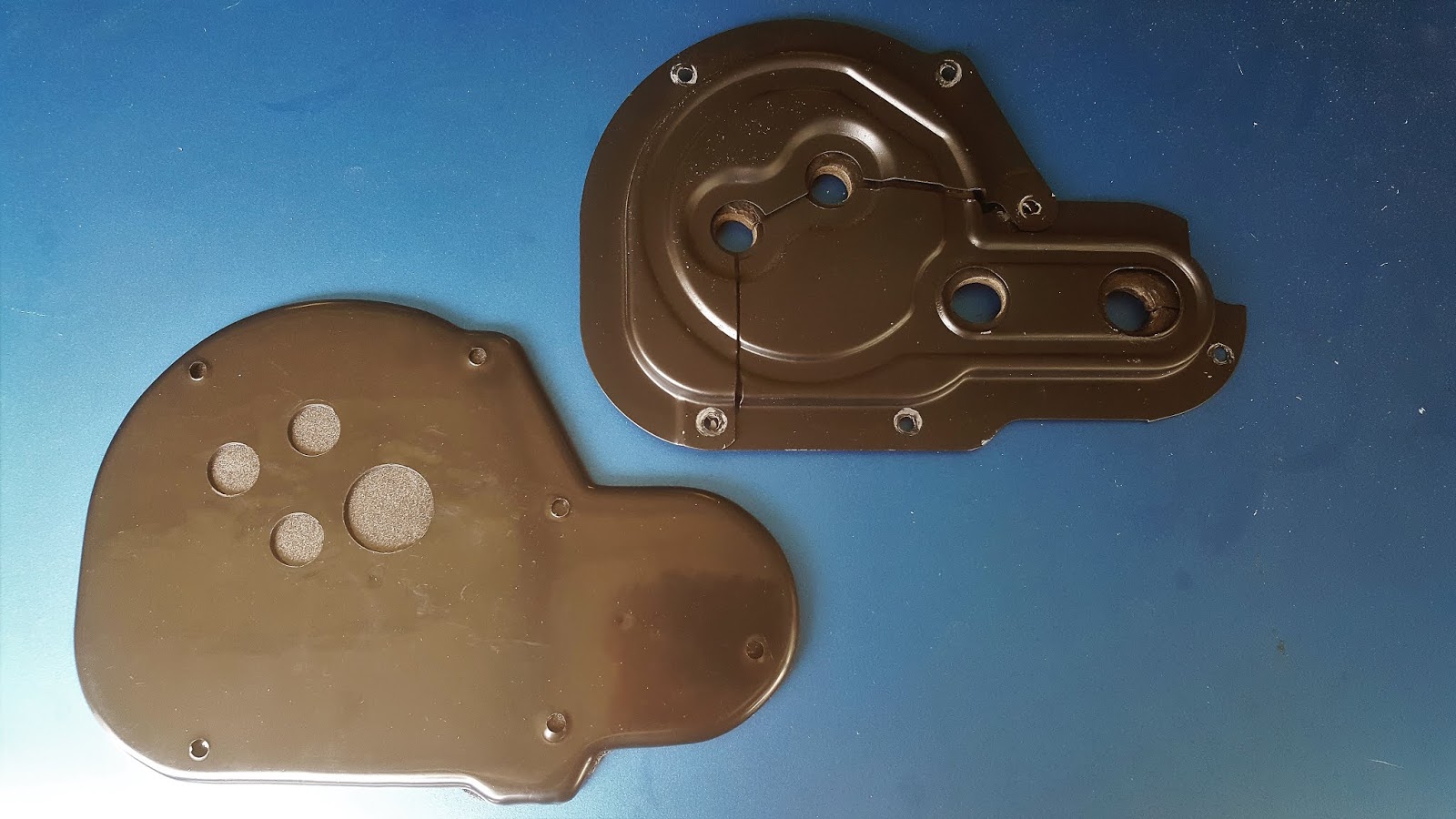
I'd hoped to reuse the original cover panel but comparing them it was quickly apparent that would not be possible as the hose configuration is entirely different. This was a little disappointing but not bad. The Classic Auto Air piece is plastic but the back is covered with a large piece of foam to help seal up the area which is no doubt helpful.

I installed the cover panel at least six different times to adjust the panel itself or its fitment.
The first time I noticed that the screws would not line up as they were too high. I considered unbolting and trying to realign the air box inside the vehicle but I decided against it as I did not want to work through the process of getting it level again. Instead, I used a file to file out the lowest hole in the center of the panel as the metal hose which protrudes through it was what caused the binding. At least the top two screw holes seemed to line up so I moved on.
The next issue was that when in place, the cover panel was not flush against the firewall because it overlapped one of the old heater hose holes in the firewall. Those holes protrude slightly so I had to mark the cover panel and cut a little recess in the back so it would sit against the firewall and seal properly.
The next chore was to find a way to route wires through the firewall. The plug for the heater control module must run through the firewall and is quite large. I tried a few different options and then decided to just have it run through this new firewall cover plate. I found a grommet that would work (albeit a little large) and drilled a hole to install it so the wires would run through and into some of the stock air conditioner holes which are not being used.
This is the final product after most of the modifications.

I went to install it again and then noticed the hole on the far right does not line up with the hole in the firewall, there is no stock hole were the middle hole on the bottom is located, but there is a stock hole about 1.5 inches to the left of it. I pulled the panel back out again, bolted the stock panel to it, and then drilled a new hole on the right and in the middle of the panel. It then went back in and finally bolted into place. Unfortunately, I spent a little over two hours screwing around with the panel trying to make it work right.

Once this panel was complete, I ran the heater hoses over to the two copper pipes shown above. The hose coming from the intake goes to the lower copper connection. The hose coming from the water pump routes through the Classic Auto Air water valve and then to the top of the two copper hose connections. The orange wire you see coming through the firewall then opens and closes the water valve when the heater is in use.
I then ran the two refrigerant hoses around to these connectors and connected them. The larger of the two connects to the compressor and the smaller of the two on the left connects to the receiver/dryer that is attached to the condensor.

With these connections complete, I spent some time using wire ties to ensure everything is held in place well. I then walked around double checking everything. I think I have everything under hood done with the exception of putting the sealing putty around where the hoses enter the firewall to make a waterproof seal. I'll do that once I'm sure nothing else needs to come apart.


With everything done, I painted the grill to clean it up a bit and then reinstalled it.

Tuesday, May 14, 2019
Preparing for Ford Nationals - AC Part 7 - Condenser & Receiver/Dryer
I removed the grill and hood support bracket today for the installation of the condenser and receiver/dryer. I took my time attaching the top and bottom mounts to the condenser while inside the comfort of the house. Once they were installed, I attached the receiver/dryer and the associated hose. The assembly was then ready for installation.
The installation of the condenser assembly was fairly straight forward. Once mounted in place with the hood support installed, I was able to connect the hard lines to the condenser and receiver/dryer. The receiver/dryer line ran perfectly through the existing lower hole in the firewall. The top condenser outlet required some adjustment to the metal portion of the hose to run through the existing hole but I managed to get it to line up well.

With the hard lines connected at the condenser, I connected the ran the hoses to their final locations and tightened those possible. I'll need to finish work on the firewall cover before I can finalize those connections.

Before I put the grill back in place, I'm going to clean it up just a bit and then add a fresh coat of black paint.
The installation of the condenser assembly was fairly straight forward. Once mounted in place with the hood support installed, I was able to connect the hard lines to the condenser and receiver/dryer. The receiver/dryer line ran perfectly through the existing lower hole in the firewall. The top condenser outlet required some adjustment to the metal portion of the hose to run through the existing hole but I managed to get it to line up well.


Before I put the grill back in place, I'm going to clean it up just a bit and then add a fresh coat of black paint.
Sunday, May 12, 2019
Preparing for Ford Nationals - AC Part 6 - AC Box Installation
With the help of my son, I installed the A/C box under the dash of the Mustang today. This required the removal of the glove box, radio, and the wiring for the A/F meter as it entered through one of the old heater hose holes. The box was actually much either to install than I expected. Due to its size, I expected it to be a pain but it was rather easy.


The box mounts in some of the stock locations which is great as there are fewer holes placed in the vehicle. I'd hoped to reuse the stock A/C plate on the firewall but the hose configuration is completely different with the Classic Auto Air system. I hoped to use the original one as it is metal and the Classic Auto Air is just an inexpensive piece of ABS plastic (Classic Auto Air version in lower left).
The A/C box tucks up fairly tight and is held in place by three bolts. It mounts to a factory tab beside the passenger cowl vent, the bracket behind the glove box in the picture below, and then a third from the engine compartment where the various hose connections are located. They are all on the passenger side thought. I'm tempted to add something behind the radio if possible to keep it level and ensure it does not move around.

I keep handling a few tasks each day. I still need to install the condenser, heater/dryer, heater hoses, refrigerant lines, control module, driver A/C vent, and all the hoses for routing the air inside the vehicle Once those are all complete, I'll still need to get the system charged. I hope to finish everything over the next week. This will give me approximately a month to drive the Mustang around and see if there are any remaining items to address before the road trip.
Preparing for Ford Nationals - Anti-Freeze Leaks
While working on the A/C install, I removed the water pump and reinstalled it with new gaskets a week ago. This was one of the steps planned for addressing the anti-freeze leaks. The second was addressing a leak from the thermostat housing.
I'm quite sure when I purchased the Mustang, there was a leak from the thermostat housing. This has continued despite switching to the Weiand Stealth intake, flat sanding the thermostat housing, and then switching to the Edlebrock intake and new thermostat housing. I'm going to try to do it perfect this time as the leak persisting with all these configurations points to it being an installation problem.
I removed the thermostat housing and you could see where anti-freeze was leaking past the gasket. As seen below, the gasket was soaked as evident by the dark blue color. I'm not sure it adhered well either as half of it just came off with almost no residue.


I believe I used Permatex Ultra Grey last time I installed the thermostat housing. This time, I'm using a new Fel-Pro 35067 gasket, Permatex Water Pump & Thermostat Housing Gasket Maker, and Loctite Thread Sealant. I'm hopeful this combination will stop the leak.
With everything apart, I cleaned off all the gasket material and then wiped down everything with mineral spirits to get it as clean as possible.


The job is now done and will have plenty of time to dry as I finish up the A/C. I'll need to touch all the bolts and clamps before filling it up to ensure nothing gets loose as it dries.
As part of this process, I also swapped out the clamps that I'm using on all the hoses. I was originally using the tower style clamps which were original to the vehicle. However, I question if they get a solid seal round the entire hose. This time I reinstalled everything with a set of Scott Drake Stainless, FoMoCo labeled worm clamps.

Saturday, May 11, 2019
Preparing for Ford Nationals - Radiator Shroud & Fan
Tonight, I finished the installation of the new Flex-a-Lite 118 Electric Fan and Champion 116-FS339 fan shroud which is custom fit to my Champion radiator.
The new fan is a 2,500 CFM fan and I'm replacing a 2,190 CFM Flex-a-Lite S-Blade 336 fan so the performance should be similar. The main difference is the new fan is much thinner (3.187" thick). I had to switch to a thinner fan in order to insert the shroud. The original electric fan just barely fit at 4" so this new fan allowed for the .75" thick Champion fan shroud.

I retained the original Flex-A-Lite 31147 adjustable fan controller. I'll need to adjust it as I don't think it is set all that well right now. However, it is connected and I took the time to carefully do all the connections properly with heat shrink.

I barely have enough space between the back of the fan and the water pump pulley for a fan belt to slide between. This is about a close as it gets.

I've had incidents when the Mustang has run hot without the air conditioning system. My understanding is the fan shroud should help this a considerable amount. I'm hopeful this improves the performance of the cooling system. It will probably help a bit more than my water pump pulley is a little smaller in diameter as it will spin a big faster now.
The original water pump pulley was 6.25" in diameter. I switched to a C6AZ-8509-G water pump pulley which is 5.82" in diameter. This will spin the water pump about 7% faster which is not much but should help a bit at idle.
Friday, May 10, 2019
Preparing for Ford Nationals - AC Part 5 - Cowl Vent Plates
I've been working periodically on the block off plates for the cowl vents which were provided with the Classic Auto Air kit. The supplied block off plates are galvanized steel discs with some foam strip around the perimeter. Before installing them, I coated them with some primer and then Krylon 1316 semi-flat black.
A little earlier this week, I removed the fresh air vent from the driver side. The vent is held in place by four nuts. The Classic Auto Air vent just had three small screw holes which did not line up with the fresh air vent holes. I drilled new ones and then used the original bolts from the fresh air vent to hold it in place.
The passenger side was a little different as it must be held in place with a few self tapping screws. Strangely, the provided covers have a hole at 12 o'clock, 3 o'clock and 9 o'clock but nothing at the 6 o'clock location. I drilled another hole so it would be held with four screws. I then screwed it in place this evening.

Wednesday, May 8, 2019
Preparing for Ford Nationals - AC Part 4 - Water Pump Pulley
I purchased a replacement water pump pulley this past week on eBay. The pulley is 5.82" in diameter versus my current pulley diameter of 6.25" While the listing stated it was 2.25" offset, it is actually closer to 2" but that actually seems to work better with the Classic Auto Air crank pulley. You can see this in my image of the original water pump pulley as it does not line up properly.
The new pulley is a C6AZ-8509-G which I believe is from a 240 ci engine. It worked perfectly for my application. The narrower diameter works with the Classic Auto Air crank pulley. Additionally, the smaller diameter will spin it a slight be faster which might be beneficial for cooling purposes.


I did not take any real pictures of the painted part. I include the pictures above with the part numbers as it is not cast into the part. However, I do have the following picture of the pulley installed.

With the water pump pulley installed, I was able to reinstall the belt and tighten up the alternator. I then installed the belt for the air conditioning. The Classic Auto Air instructions indicate you need a 51" belt but that was too long. I actually found that a 49.5" belt works best with the amount of adjustment possible with the A/C belt tensioner.

Sunday, May 5, 2019
Preparing for Ford Nationals - AC Part 3 - Control Panel & Bench Testing
This evening, I rebuilt the stock A/C control panel to using the parts from the Classic Auto Air kit. This portion of the kit left a bit more to be desired that the other parts that I've installed to this point.
I started working through the instructions by installing the new fan motor control. This replaces the stock control and is expected to mount using the same bolts. However, when I used them, the switch was oriented such that the low, medium, and high positions were available but off was not. I had to drill a new mounting hole for the lower side of the bracket so it would align properly.

The kit uses the stock levers for the mode (passenger, defrost, floor) and temp (cool, heat). Using the stock levelers allows you to retain the stock knobs. However, the new fan motor switch comes with a knob which does not resemble the other knobs. I attempted to use the stock knob but the set screw is not long enough to hold onto the new thin lever so I ended up going to the store for a new set screw which worked.

There is a new bracket which is installed in place of the OEM vacuum module which changes the A/C mode. One end has a tab which slides into a hold in the stock control panel and bolts through a hole in the other side. This new bracket and the bolt were supplied by Classic Auto Air but the hole in the bracket was not the right size for the bracket. No big deal but it is strange to keep needing to modify items for something referred to as a Elite Fit.

Once I finished with the controls, I decided to follow the process to bench test the entire A/C unit. You essentially take the entire A/C box, control unit, and wire it all up outside the vehicle. You take steps to cycle through the settings on the control unit so it adjusts to the extremes of each of the lever moves. Once this is done, you can then test to ensure the floor, defrost, and passenger air controls as well as the heater water valve. Everything works great so I'm ready to start moving on to the next steps.
Wednesday, May 1, 2019
Preparing for Ford Nationals - AC Part 2 - Compressor Install 2
After work today, I picked up a Fel-Pro Timing Cover Gasket Set (TCS-45008), Permatex Water Pump & Thermostat Housing Gasket Maker, a tube of Loctite Thread Sealant, and 9' of 5/8" heater hose. After eating dinner, I started work on the air conditioning system.
I installed the crank pulley which came with the Classic Auto Air System. I then moved on to reinstalling the water pump. Afterwards, I installed the alternator and the alternator bracket. This allowed me to install the front compressor bracket and then the compressor itself.

I then encountered my first problem when I went to install the newly painted water pump pulley. I found that it no longer fit as it contacted the crank pulley. I reviewed the paperwork and it seems that the system will only work if you have a water pump pulley under 6".

This was a bit of a disappointment as I still want to buy a radiator shroud and a new electric fan that will work with it. I really didn't want to spend more money or different parts when I expected the water pump pulley to work. However, I did find a smaller water pump pulley 5.82" on eBay which is an OEM Ford pump with the same offset so I purchased it tonight. I'll need to switch to working on something else as it will take it a bit to arrive so I can finish up the under hood components.
The label and numbers on the compressor are not visible when installed. I took the following picture to reference those numbers if needed later.

I installed the crank pulley which came with the Classic Auto Air System. I then moved on to reinstalling the water pump. Afterwards, I installed the alternator and the alternator bracket. This allowed me to install the front compressor bracket and then the compressor itself.


This was a bit of a disappointment as I still want to buy a radiator shroud and a new electric fan that will work with it. I really didn't want to spend more money or different parts when I expected the water pump pulley to work. However, I did find a smaller water pump pulley 5.82" on eBay which is an OEM Ford pump with the same offset so I purchased it tonight. I'll need to switch to working on something else as it will take it a bit to arrive so I can finish up the under hood components.
The label and numbers on the compressor are not visible when installed. I took the following picture to reference those numbers if needed later.

Subscribe to:
Posts (Atom)